


Smart Top Link

PART NO: ACX5382160
LEVEL UP
Smart Top Link keeps a mounted fertiliser spreader level creating a precise spread pattern. Hydraulic top link is controlled by two sensors, fitted to the front and rear of the spreader, leading to better crop growth and increased yield.
Available
Valtra Unlimited (factory installation)
AGCO PARTS (retrofit for all AGCO brands)
Only in Europe

OVERVIEW
- Levelling functionality with real time adjustment
- Sensors that measure the distance to the ground
- Improved spread pattern
- Reduces the coefficient of variation
- Even crop growth
- Fits any fertilizer spreader
- Connected to ISOBUS
- Hydraulic top link controlled
REQUIREMENTS
ISOBUS
Tractor must be ISOBUS compatible to allow communication between the implement and the terminal.
HYDRAULIC FEATURES
System requires load-sensing hydraulic lines and a hydraulic top link installed on the tractor
QUICK GUIDE
HOW TO USE
MODES

OFF
When you want to start using Smart Top Link,
Press “AUTO OFF” button to activate the system.

PAUSE
Tractor is not moving, or speed is over 25km/h.
Adjust the tractor speed and the system will switch to “AUTO”.
If this doesn’t work, in some special cases the sensor data is not reliable enough for automatic control. In this case, see Fault codes.

AUTO
Top link moves automatically to keep the implement levelled.
Note that once tractor starts moving, the top link will start properly moving after 20 seconds, even with “AUTO”.

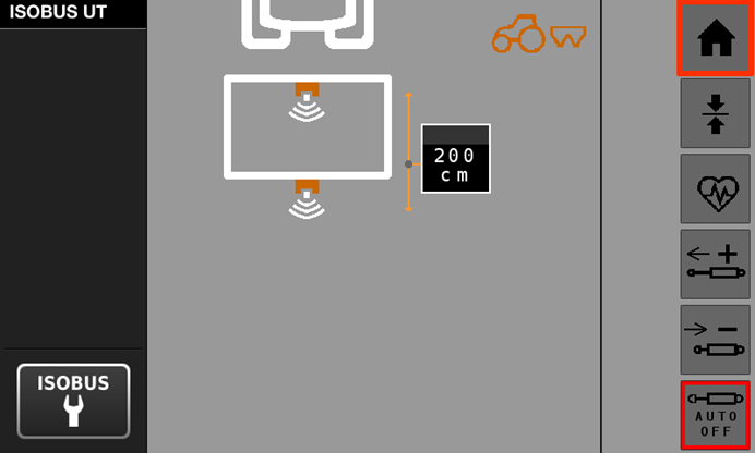
Main View
1. Settings menu
2. System status (OFF/PAUSE/AUTO)
3. Current angle of implement
4. Help view
5. Manually extend top link
6. Target angle
7. Manually shorten top link
8. Current height of implement
9. AUTO ON/OFF button to Smart Top Link
QUICK ANGLE FIX
If the top link should fix the angle quickly (for example after refill), it is recommended to lower the tractor hitch (by at least 5% in hitch height) for filling. After lifting it back up, the Smart Top Link system will detect the refill and correct the spreader angle quicker (within one minute). Also note that if the spreader angle is more than 5 degrees from the target, the system will not correct the angle for safety reasons.
HEIGHT ADJUSTMENT
You can also observe the height of the implement.
The correct height for the implement is often mentioned in the implement manual.
USING THE SYSTEM IN LARGE ANGLES (target angle 5-6 degrees)
Normally setting the target angle to the screen is a valid way to use the system. When target angle is 5 degrees or more, it is recommended to set the spreader at the desired angle, then adjust the sensors in a way that they are pointing straight down to ground. After this, perform calibration, and then use the system normally (with target angle on the screen at 0). Remember to adjust the sensors again when spreading at smaller angles.
On transport, the Smart Top Link should be turned off for safety reasons.
Use the system only in field conditions (under 25 km/h), system must be OFF, when working around the implement.
TO THE TRACTOR

Here are the installation instructions for the parts that are installed to different tractors.
Each variation for tractors contains a video and downloadable quick guide that can be printed out to support the installation.
TO THE TRACTOR - IN THE BOX
The parts that are installed to the tractor and provided with the Smart Top Link are hydraulic parts, hydraulic block, ECU, harness and mount (according to your order). Scroll down for quick guide instruction for specific tractor brands.
For the remaining items and hoses which will connect the hydraulic block to the tractor, there is a list of suitable items presented with each mounting bracket
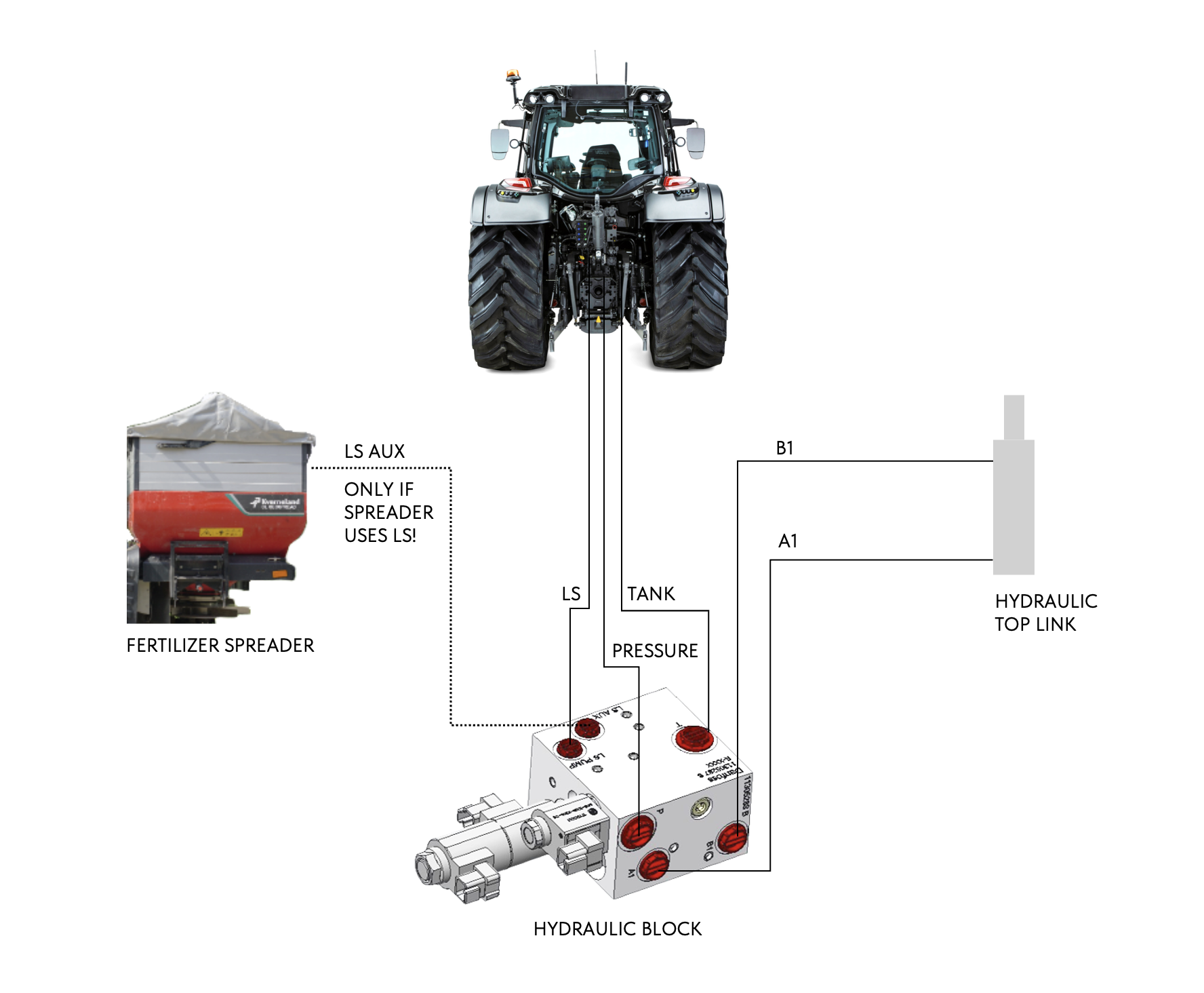
Hydraulic diagram
Hydraulic connections for the system presented in the following picture.

Hydraulic block
1. LS PUMP (for tractor LS line) M14 ISO 6149-1
2. LS AUX (for implement LS hose) M14 ISO 6149-1
3. Tank M22 ISO 6149-1
4. Pressure M22 ISO 6149-1
5. Top Link + M18
6. Top Link M18

Hydraulic connectors provided with the system are LS AUX with 3/8” female quick coupler and two ½” female quick couplers for top link hoses.
1. 3/8” quick coupler with 90-angle pipe and M14-3/8” nipple
2. ½” quick coupler with M18-1/2” adapter and washers
3. ½” quick coupler with M18-1/2” adapter and washers

Installation orientation of the hydraulic block is important for the correct operation, always install the hydraulic block in a way where the magnet valves are in horizontal direction.

ELECTRICAL CONNECTIONS HYDRAULIC BLOCK
1. ”Y1”, plus-side valve
2. ”Y2”, minus-side valve
3. ”Y3”, safety valve

ELECTRICAL CONNECTIONS ECU
A. Hydraulic connector
C. ISOBUS connector
D. Sensor harness
B. -

ECU LIGHTS
1. Operating Status (ECU) Green light/ Not blinking
- If green light is blinking once a second, complete SW update
2. Status 1 (ISOBUS) Green and red lights blinking
3. Status 2 (Sensor CAN) Green and red lights blinking
AIRING THE SYSTEM
After installing the hardware, using the Smart Top Link, move the top link from the shortest position to the longest position three times to air the system. Otherwise there might be air trapped in the system and it might not work correctly.
INSTALLING TRACTOR PARTS TO THE SPREADER

The hydraulic block and ECU can also be installed to the implement.

In these example pictures also the hydraulic lines have been splitted from the spreader (Amazone).
FENDT 500, 700, 800 AND 900
Fendt 500/700/800/900
MASSEY FERGUSON 6S/7S
MASSEY FERGUSON 6S/7S
VALTRA N-, T-SERIES
VALTRA N-, T-SERIES
VALTRA Q-, S-SERIES & MASSEY FERGUSON 8S, 9S
VALTRA Q-, S-SERIES & MASSEY FERGUSON 8S, 9S
TO THE IMPLEMENT
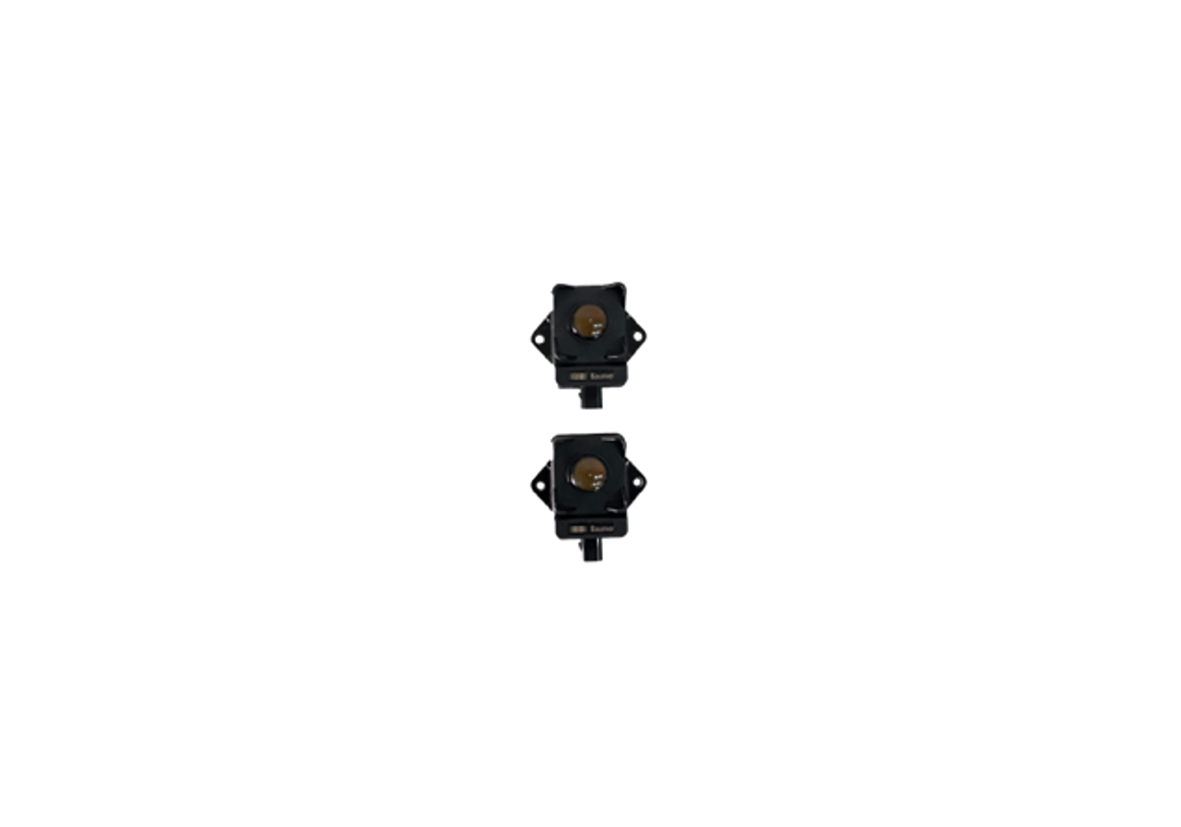
At this point, installation for the Smart Top Link tractor parts has been completed. Smart Top Link system uses two sensors, which need to be installed to the implement along with the sensor harness. Follow these steps to complete the sensor installation.


1. Power on the machine and make sure ISOBUS UT is activated from tractor terminal. Open ISOBUS UT view from the terminal and wait for application to load. After loading, display shows the Home Screen view of the Smart Top Link system.

2. Connect the sensor cables to the 4-pin socket at the rear of the tractor and the other end of it to the sensors.

3. Turn on the sensor identification mode from your tractors ISOBUS display.
- This will make sensors blink in different colours.
- Mount sensor 1 (Blue) to the rear of the implement
- Mount sensor 2 (Green/Yellow) to the front of the implement.

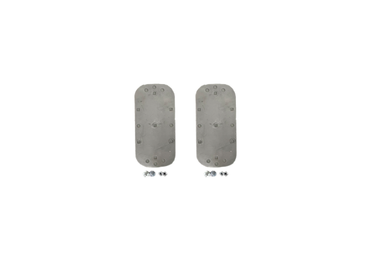
4. Attach the sensors to the steel plates

5. Installing the sensors to the implement
- Pointing straight down to the ground
- Make sure sensors are underneath the spreading disc
- At the minimum height of 30cm from the ground while the spreader at its operating height. Sensors should be approximately at the same height.
- Both sensors should be in line, however there is a 40cm tolerance. Distance between sensors should be minimum of 70cm.
- Installing them to the middle of the implement is preferred. If the crop is very thick, install the sensors near the tire track to get a better view of the ground.
- If sensor is too close to the frame of the implement, there might be reflections which affect the sensor reading in a negative way
- Make sure that the sensors do not collide with ground surface when lowering the implement!

IMPLEMENT EXAMPLES
Bogballe mounting the radars.

IMPLEMENT EXAMPLES
Kverneland mounting the radars.

6. Fix loose objects near the sensor
- Chains, cables and hydraulic hoses

7. Fasten the cables
- Do not tightly bend the cables.
- All cables should be securely fastened to the implement's frame.
- Make sure they are not pinched between metal objects.
- Cables shouldn’t affect the movements of any implement parts.
- Ensure that the connectors are properly locked in place.
- Make sure that the cable is not too loose, being in a risk of interfering with ground surface.
- Make sure that the cable is not too tight, being in a risk of braking while the implement is moved.

8. Set implement to working height and make sure it is level with the ground surface.
Next, do the calibration.
CALIBRATION
Calibration procedure needs to be executed every time installation of sensors is changed. It is preferred to perform calibration with an empty spreader.
- Make sure fertiliser spreader is installed to rear linkage correctly.
- Lift fertiliser spreader to operating height (you can check spreader manual for precise height requirements).
- Drive on a flat, field surface (calibration on concrete or asphalt can result in poor calibration)
- Make sure the fertiliser spreader is level by measuring front and rear of the spreader manually.
Main View
1. Settings menu
2. System status (OFF/PAUSE/AUTO)
3. Current angle of implement
4. Help view
5. Manually extend top link
6. Target angle
7. Manually shorten top link
8. Current height of implement
9. AUTO ON/OFF button to activate and deactivate Smart Top Link function

Step 1
Measure distance between the sensors.
Open the settings and add the value to the field.
Step 2
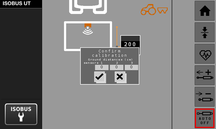
Press calibration button and check that the sensor values seem realistic. You can measure the sensor heights with a measuring tape.
Step 3
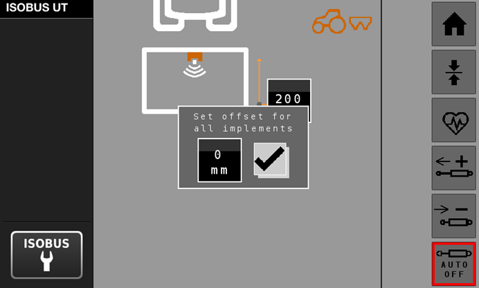
Measure the distance of the spreading disc to the ground and enter that into the off set values.

Enter measured value into the offset.

Calibration completed

After calibration
To check that the Smart Top Link is working correctly, you can complete a following procedure
- Manually adjust the implement to -4 degrees
- Lower hitch (by at least 5%)
- Lift hitch back up
- Drive aroud on a field for three minutes
- Implement should be levelled at one minute mark
MANUAL
DIAGNOSTICS

- Ground distance values (raw, filtered, and calibrated values)
- Average ground distance value.
- Sensor statuses.
- Sensor quality values (reliability of the data).
- Calibration values.
- Upper limit of the height range (can be adjusted).
- Upper limit of the height range (can be adjusted).
- Tilt angle degrees.
- Offset values.
- Software version number.
- NEXT VT (change the ISOBUS UI priority when multiple ISOBUS implements)
SAFETY
Displays and Control Consoles
Make sure that you are familiar operating the tractor and implements and react to any warnings given by tractor.
If Smart Top Link System behaves faulty or gives Diagnostic Trouble Codes, refer to Maintenance manual for further descriptions of causes and resolutions or contact your local AGCO service dealer.
Hydraulic Safety
**Use Only AGCO Approved Top-Link Cylinders
When installing or servicing a hydraulic system or hydraulic components, be aware that hydraulic fluid may be extremely hot and under high pressure. Never attempt to open or work on a hydraulic system with the implement running or under load. The implement or machine must remain stationary during installation or maintenance.
Take precautions to prevent foreign material or contaminants from being introduced into the implement hydraulic system.
Use protection gears and stand clear of the implement when starting the system for the first time after installing or servicing hydraulic components in case a hose has not been properly connected or tightened.
Electrical Safety
Verify that electric harness cables are intact and connected correctly. To avoid entanglement hazards, route cables and harnesses carefully on the implement. Leave enough space for movement and make sure that moving parts cannot touch the cable.
Machine Safety
Make sure that top link has enough range for movement and therefore doesn’t cause implement collision with the tractor or ground surface.
When doing maintenance or other works near the top link or the implement outside the tractor, make sure that the smart top link is switched off.

SOFTWARE UPDATES
Latest software version 0.5.13 can be found in the "JCA Wind Tools" app or "PTx Wind Tools" app.
Download and install the app from your mobile device application store.
Latest improvements:
- Improved sensor filtering logic to improve behavior in difficult environments
- Improved UI responsiveness
- Fixed issue where implement icon and target angle are out of sync
- Fixed calibration getting stuck
- Added cancelling button to first calibration button
- Error codes activation adjusted
- Improved top link controlling logic to make it more responsive
- Improved accuracy of fast leveling
- Main screen height bar graph changed from 0-100cm to 60-100cm
FAULT CODES
| NUMBER | TITLE | DESCRIPTION | SEVERITY | |
| 1 | Sensor Configuration Error 1 | Check sensor connections/statuses and sensor configuration settings. | Medium | |
| 2 | Sensor Reversible Error 2 | Internal sensor error, check sensor temperatures and wiring harness. | Medium | |
| 3 | Sensor Irreversible Error 3 | Internal sensor error, contact AGCO dealer for a replacement part. | High | |
| 4 | Invalid Data Error 4 | Check sensor positions (eg. too close to the ground, reflecting surfaces). | Low | |
| 5 | Ground Distance Error 5 | Check if any objects are blocking sensor vision and confirm distance values are inside the limits. | Medium | |
| 6 | CAN ISOBUS Communication Error 6 | Check ISOBUS wiring harness and cable connection | High | |
| 7 | CAN Sensor Communication Error 7 | Check sensor wiring and cable connection | High | |
| 8 | Open Circuit in plus valve 8 | Open circuit in plus valve harness of the hydraulic block | Medium | |
| 9 | Short Circuit in Plus Valve 9 | Short circuit in plus valve harness of the hydraulic block | High | |
| 10 | Open Circuit in Minus Valve 10 | Open circuit in minus valve harness of the hydraulic block | Medium | |
| 11 | Short Circuit in Minus Valve 11 | Short circuit in minus valve harness of the hydraulic block | High | |
| 12 | Open Circuit in Safety Valve 12 | Open circuit in safety valve harness of the hydraulic block | Medium | |
| 13 | Short Circuit in Safety Valve 13 | Short circuit in safety valve harness of the hydraulic block | High | |
| 14 | Sensor 1 Bad Signal Quality Error 14 | Check sensor positions and for possible blocking objects, reflecting surfaces or loose objects near the sensor | Medium | |
| 15 | Sensor 2 Bad Signal Quality Error 15 | Check sensor positions and for possible blocking objects, reflecting surfaces or loose objects near the sensor | Medium | |
| 100 | Calibration warning | Machine must be stationary when calibrating | Low |
Note!
Smart Top Link is ment to be used in field conditions. Driving on farm yard or gravel etc. Might trigger error codes 14 and 15 (Sensors 1 & 2 bad signal quality)
FAQ
Does the Smart Top Link change the application rate?
- NO, Smart Top Link adjust the angle of the machineDoes it automatically adjust the implement height also?
- NO, but with Smart Top Link you’re able to monitor the height very accurately, making adjustments if needed.Does the crop affect the measurement?
- NO, the sensor measures to solid ground.Does it work on hilly fields?
- YES, it just keeps the implement parallel to ground (ground that is under the spreader. We use filter on the control system, so small changes on the ground doesn’t matter)Can I use other ISOBUS implement at the same time
- YES, ISOBUS screen will have button to change between the screensCan I use my fertilizer spreader that has LS hydraulics together with Smart Top Link?
- YES, Smart Top Link has built-in splitter for implements LS aux hose
Does the screen view have to be always visible in the terminal?
- NO, Smart Top Link can also run in the background.Can this be used on other implements?
- NO, we have just designed this for use with a fertilizer spreader.Can this be used on any tractor?
- NO, At the moment we have only tested the Smart Top Link to work on AGCO machines.- Do I plug the system straight to the normal tractor valves?
- NO, system comes with additional hydraulic block, which is connected to tractor LS hydraulics.
- Why does the main screen show "PAUSE" text instead of "AUTO"?
- PAUSE text indicates that the system is not currently controlling the toplink automatically. The reason could be that tractor is stationary, tractor speed is over 25 km/h, or there is an active error in the system.
- When I'm driving on the road, there is a small extra symbol on the screen. What does it mean?
- Tractor is driving over 25 km/h, and system is on PAUSE because of safety reasons
- I can't activate automatics, or automatics go off by itself
- There has been a critical error on the system for over 10 seconds. Check active error codes and act according to the error code information. System also deactivates when tractor and/or system is restarted
- There is red triangle blinking in the bottom of screen
- Red triangle alerts of active errors in the system. Press "info" button on the user interface for more details.
Why doesn't my top link move on AUTO?
After tractor starts to move, it takes 15-20s for the top link to start moving. If the current angle is more than 5 degrees from the target angle, system doesn't move the top link due to safety reasons.
Why is the top link so slow on AUTO?
System is designed to compensate the angle change when spreader is emptying, this is normally a slow change. For larger angle corrections that need to be done quicker, see QUICK GUIDE / HOW TO USE / QUICK ANGLE FIX
I keep getting error codes 14 & 15. What can I do?
Make sure that the sensors are installed correctly and there are no loose objects like cables or chains near the sensor, even above the sensor (see picture in QUICK GUIDE / TO THE IMPLEMENT / Step 6). Sometimes the surface under the sensor can cause the error, for example when driving on farm yard or asphalt, especially if it's wet.